Table of Content
- Introduction.. 3
- The concept of Interpolation and Decimation.. 4
- Major Features of SoulRA DUC.. 6
- Major Features of SoulRA DDC.. 8
- SoulRA DUC 3X, 5X and block diagram with CIC.. 9
- Matlab Models for SoulRA DUC and DDC.. 12
- Application diagrams for SoulRA DUC and DDC.. 19
- Lattice Synthesis results for SoulRA DUC.. 20
- AXI Interface for the DUC/DDC.. 22
- Support Information.. 22
Section 1
Introduction
Signal interpolation and decimation are fundamental to the DSP processing in 5G mobiles, 5G base-stations, Software Defined Radio (SDR), medical electronics, Radio Astronomy, Satellite communications and military Radar and Sonar.
The FPGA and ASIC IP which is described in this document performs Signal interpolation (Digital Up Converter) and Signal Decimation (Digital Down Converter).
Sample rate conversion (SRC) is the process of changing the sampling rate of a data stream from a specific sampling rate (e.g. the input/output hardware rate) to another sampling rate (e.g. the application rate).
SRC is the basic idea behind interpolation and decimation. In Interpolation structures such as a CIC interpolator the sample rate is usually multiplied by an integer and intermediate samples are generated.
In decimation structures such as a CIC decimator the sampling rate is reduced by and integer and say (N-1) out of N adjacent samples are dropped.
SRC is necessary component in many of today’s applications including Digital Mixing Consoles, Digital Audio systems, CD-R, MD Recorders, Multitrack Digital Audio and Video Tape Recorders, Digital Audio Broadcast Equipment, Digital Tape Recorders, Computer Communication and Multimedia Systems. A very high-quality sample rate converter is required; Sampling rate conversion involves some pre-filtering which is addressed in this document.
Section 2
The concept of Interpolation and Decimation
Interpolation involves zero stuffing that is increasing the sample rate of a signal in a Cascaded Integrator Comb (CIC) structure. Decimation involves dropping samples say dropping every 3 out of 4 samples.
The CIC filter is a multiplier free filter that is perfect for large changes in sampling rate. It was proposed by Eugene Hogenauer in 1981 [1]. CIC filters are created by integrating basic 1-bit integrators and 1-bit differentiators.
It is also well suited for FPGA and ASIC implementation with very low dynamic power and very high throughput and a K stage pipelined structure. The CIC filter can also be implemented very efficiently in hardware due to its symmetric structure.
CIC structures allow high ratio decimation and Interpolation with very low power for FPGA implementation. This structure avoids all multipliers hence it peak clock frequency is much higher. The fact that CIC filters only use Integrators and Comb leads to far lower FPGA resources – no DSP blocks and lower dynamic power.
The other type of decimation structure is a Fir filter followed by a down sampling stage. The down sampler selects one out of N succeeding samples where N is the decimation ratio. The decimator is usually preceded by a FiR stage.
Interpolator transfer function
Comb filter transfer function:
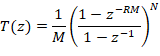


The CIC filter will have N comb stages running at and followed by a zero-insertion stage followed by a N integrator stages running at .
Decimator block diagram using CIC
CIC decimator block implemented in SoulRa IP
Section 3
Major Features of SoulRA DUC
In this Structure a Dual channel I and Q has half band filters preceding the CIC filters, the half band filters are highly efficient as 50% of the filter coefficients are zero
The problem is register flow in the integrator stages is a reality for all CIC filters. If the Integrator bit width is adjusted correctly the problem of register overflow can be overcome in CIC filters. In the SoulRA Implementation the Integrator BW is automatically adjusted for bits where W0 is the bit width at integrator input. Where K = number of integrator stages and N is interpolation ratio.
Example K= 5; N = 16; W0 = 16 bits and Wint = 16 + 5*log (16) = 36.
Table 1 Major features of SoulRA DUC IP
| Up conversion Ratio | 2:128 or 2:256 |
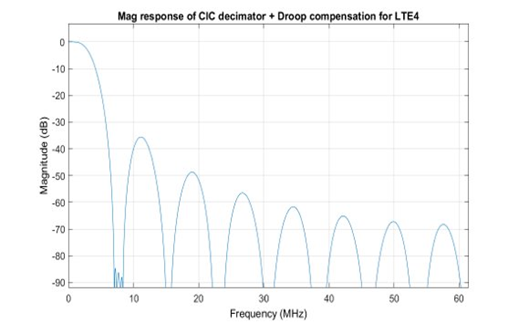
| Droop compensation | Built in to compensate stage droop and CIC |
| CIC Bit width growth | Built into CIC structure |
| Bus Interface | AXI-4 and Wishbone |
| Availability of Odd conversion Ratios | 1:3 and 1:5 are both available within the IP; 1:7/1:9 and 1:11 can be provided in a customized version |
| DAC compensation | Multiband Inverse Sinc Filter for DAC compensation is included – and its bypassable |
| LUT Count | LUT4 (1676+5=1681) ; PFU Registers (361+2133=2494) |
In the next figure a 3X Interpolation DUC has been described. This is available as a part of the SoulRA IP.
Section 4
Major Features of SoulRA DDC
Table 2: SoulRA DDC features
| Down conversion Ratio | 128:2 |
| Droop compensation | Built in to compensate stage droop and CIC |
| CIC Bit width growth | Built into CIC structure |
| Bus Interface | AXI-4 and Wishbone |
| Availability of Odd conversion Ratios | 3:1 and 5:1 Down conversion are available |
| DAC compensation | Multiband Inverse Sinc Filter for DAC compensation is included |
| LUT Count | LUT4 (1700) ; PFU Registers (2600) |
Section 5
SoulRA DUC 3X, 5X and block diagram with CIC
Figure 5 illustrates one option from SoulRA which is a DUC with 3X Interpolation.
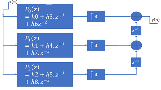
SoulRa Logic block for 3X Interpolation of a single incoming data stream.
The 3X interpolator is especially required for those DUC applications where one needs a multiple of 3 sampling rate conversion.
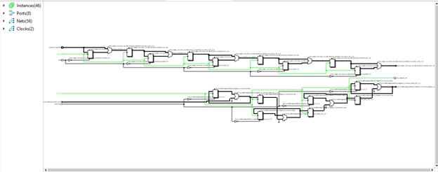
The second diagram illustrates the Synthesized version of the 3X interpolator.
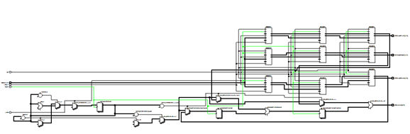
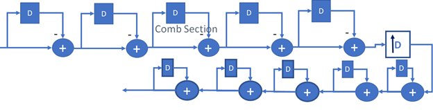
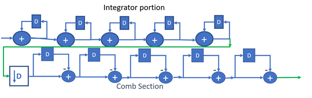
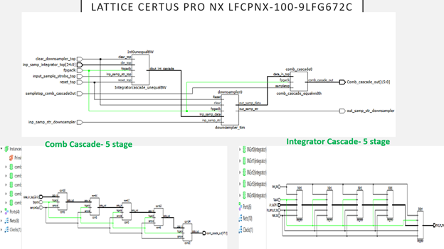
Figure 6 illustrates the block diagram of a Digital up converter for a 5 stage CIC up sampler from SoulRA.
The 5 stage up sampler is designed with 5 Comb stages and 5 Integrator Stages.
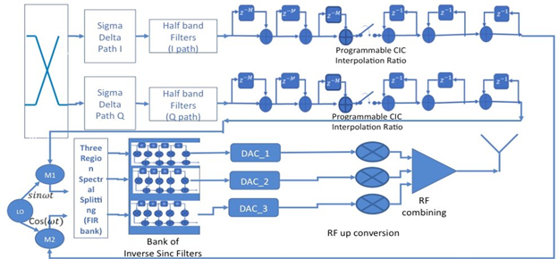
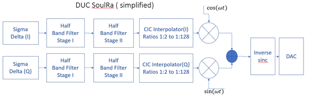
Figure 7: DUC with Half band filters and 3 stage Comb Stage, Zero stuffing and 3 stage Integrator
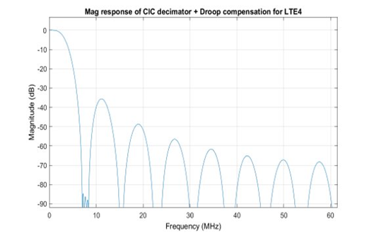
The DUC block diagram shows two separate I and Q channels with half band filters which have odd order and reduce the number of multiplications. This is followed by a three to five stage CIC filter. The CIC filter is followed by the Droop compensation filter which corrects the CIC droop.
There is a by-passable magnitude adjustment block that performs programmable shifting right after the CIC filter.
Summary of IP:
* The FIR filters preceding the CIC stage operate at reduced clock rates minimizing power consumption in high-speed hardware applications
* CIC filters used in this IP do not require any coefficient registers or coefficient loading time. The CIC filter arithmetic only requires addition and subtraction allowing very high clocking rates and very low dynamic power compared to multiplied based FIR filters.
* A single lowpass filter can perform as a narrow =band lowpass with very minimal power and complexity. This is why CIC filters are so attractive in decimating and interpolating DSP systems.
Section 6
Matlab Models for SoulRA DUC and DDC
SoulRA has created an extensive library of MATLAB models. The first example of simulation is an 8X CIC filter with 3 stages.
Matlab Models
Interpolation Filter
Stage 1: 2X Interpolation; alpha =0.5 “bandlimitedness” factor of 0.5
Use 2×2 samples
>>upfac =2; alpha = 0.5; h1 = intfilt(upfac,2, alpha);
>> fvtool(h1);
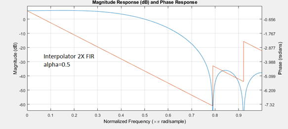
Table 3: FILTER COEFFS
| COEFF 0 | -0.092757423962 |
| COEFF 1 | 0 |
| COEFF2 | 0.5861884 |
| COEFF3 | 1 |
| COEFF4 | 0.5861884 |
| COEFF5 | 0 |
| COEFF6 | -0.092757424 |
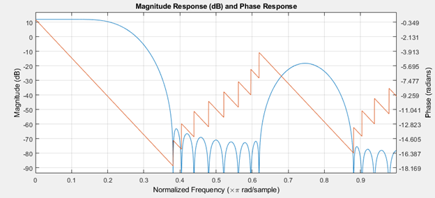
Interpolator 4X FIR with Code

lowp = fir1(20, alpha);
rng(‘default’)
x = filter (lowp,1, randn(2000,1));
xr = upsample (x,4); y = filter (h2,1, xr);
// Produces up-sampled and filtered data
// filter it using h2 filter
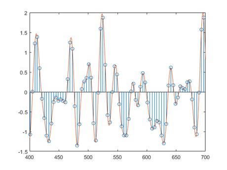
Example of 4X Interpolation
lowp = fir1(20, alpha); rng (‘default’);
x = filter (lowp,1, randn(2000,1));
xr = upsample(x,4);
y = filter (h2,1, xr);
delay = mean(grpdelay(h2));
y (1: delay) = [];
stem (1: upfac:upfac*length(x),x)
hold on
plot(y)
xlim([400 700])
Interpolation Filter
Stage 1: 2X Interpolation; alpha =0.5 “bandlimitedness” factor of 0.5
Use 2×2 samples
>>upfac =2; alpha = 0.5; h1 = intfilt(upfac,2, alpha);
>> fvtool(h1);

Table 4: FILTER COEFFS
| COEFF 0 | -0.092757423962 |
| COEFF 1 | 0 |
| COEFF2 | 0.5861884 |
| COEFF3 | 1 |
| COEFF4 | 0.5861884 |
| COEFF5 | 0 |
| COEFF6 | -0.092757424 |
Interpolator 4X FIR with Code
Table 4: FILTER COEFFS
| COEFF 0 | -0.092757423962 |
| COEFF 1 | 0 |
| COEFF2 | 0.5861884 |
| COEFF3 | 1 |
| COEFF4 | 0.5861884 |
| COEFF5 | 0 |
| COEFF6 | -0.092757424 |
Interpolator 4X FIR with Code
Table 4: FILTER COEFFS
| COEFF 0 | -0.092757423962 |
| COEFF 1 | 0 |
| COEFF2 | 0.5861884 |
| COEFF3 | 1 |
| COEFF4 | 0.5861884 |
| COEFF5 | 0 |
| COEFF6 | -0.092757424 |
Interpolator 4X FIR with Code
Section 7
Application diagrams for SoulRA DUC and DDC
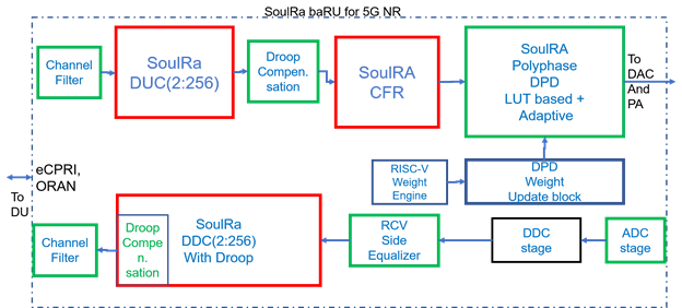
SoulRA offers the DDC and DUC blocks separately. In this diagram, the DUC output feeds a Crest Factor reduction block (also available from SoulRA) and a DPD bloc. The DUC is a major part of an 5G RU for the transmits chain.
The receiver path illustrates an Equalizer block from SoulRA followed by a DDC block which is the subject of the current document. The DDC part is output is further fed down to a Channel selector and QAM demodulator.
Section 8
Lattice Synthesis results for SoulRA DUC
CIC half band filters and deriving the Half band filter specifications
Section 9
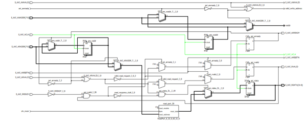
AXI Interface for the DUC/DDC
| LUT4 | PFU Registers | IO Buffers | ||
| AXI-4 | 1676 | 2133 | 96 |
AXI Subblock of the DUC/DDC
Support Information
Email: tim@soulra.net
spondon@soulra.net