Digital Pre-Distortion Product Brochure
Industry Leading DPD solutions for FPGAs/eFPGAs and ASICs
Table of Contents
- 5G transmit Chain blocks including DPD.. 3
- Role and Block Diagram of DPD block. 4
- DPD Key Features. 7
- DPD simulation results in MATLAB. 9
- Metrics for a DPD corrected amplifier 11
- DPD Interfaces. 12
- DPD Models Hammerstein.. 13
- Support 13
SECTION 1
5G transmit Chain blocks including DPD
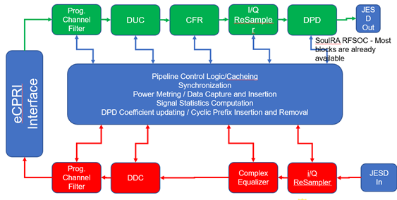
In this diagram the DUC, CFR and DPD blocks are shown cascaded the DUC followed by the CFR and the CFR in turn followed by the DPD block. The DPD block directly drives a DAC which drives the main Power Amplifier. The CFR from SoulRA is designed to alter its performance with the QAM order. This reduces the PAPR and corrects for EVM.
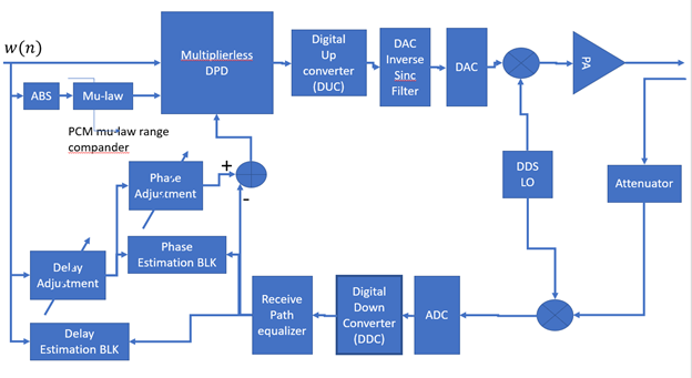
The DPD block with SoulRa is a offered as a part of a cascade of three blocks or a stand alone block by itself. The DPD block is further comprised of the DPD core, Phase adjustment block, Delay adjustment block which estimates the loop delay for the DPD design.
Section 2
Role and Block Diagram of DPD block
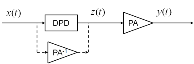
Digital Pre-distortion corrects for amplifier non-linearity in WiFi-6 WiFi-7, LTE-4G and 5G.
The amplifier non-linear effects for specifically AM-AM and AM-PM nonlinearities are illustrated in the block diagram.
The nonlinearity problem becomes worse when the QAM order is higher 256 or more and the subcarrier spacing is lower as in LTE-4G.
The DPD is implemented in ASIC or FPGA form combined DPD input with come from IFFT/Cyclic prefix blocks and DPD output goes to DAC or DUC.
We must learn the nonlinear model of the amplifier first to compute the DPD coefficients one acceptable way is termed as the Parallel Hammerstein model.
A short note on the features of the DPD block.
The Core DPD block works to reduce non-linearity and memory affects of the Power amplifier. It corrects for AM/AM distortions and AM/PM distortions of the Power Amplifier
DPD improves the ACLR, IP3 and EVM for the DPD + power amplifier chain.
The DPD design utilizes both direct learning and indirect learning to compute the internal parameters of the DPD. These learnt coefficients and LUT lookup values can be stored in External DRAM or as an internal Fast loading cache. This way the DPD allows storage for coefficients of up to 4 or 6 different Power amplifiers
The DPD is independent of the amplifier operation band it can be 2.45 GHz or 915 MHz or 5.8 GHz
The architecture of the DPD at boot-up is patented it takes under 8 clock cycles to have all coefficients loaded into the DPD
The DPD is build around a core Hammerstein model which features a non-linear block cascaded with a linear block. This matches with the corresponding model for the Power amplifier including its non-linearity and its memory effects.
The package for the DPD includes a MATLAB Model for the DPD along with a MATLAB Hammerstein model for the PA.
DPD internal architecture is a unique highly pipelined Linear stage with adaptive algorithms where is coefficient updates are also pipelined.
Section 3
DPD Key Features
| DPD from SoulRA | |
| ACLR = -40dB ( 5G requirement = -32dB) | ACLR = -45dB only simulated for 4G LTE = 20 MHZ BW |
| Signal BW > 200MHz for a 250 MHz Clock more than sufficient for 5G-NR | LTE Signal BW |
| RTL availability – NOW! On multiple FPGA Platforms , MATLAB Model available | Hard Macro and RTL |
| Interfaces AXI-4 | AXI-4 |
| Maximum attainable power efficiency > 52% | 50% efficiency |
| Weight update using NLMS, RLS Both Polynomial and Neural Network DPDs are available | Weight update only LMS 1 output per cycle |
Summary: Fast stream DPD offers higher throughput, more than adequate ACLR and Signal BW > 300 MHz sufficient for 5G.
LUT-6 Count with AXI-4 Interface = 5500 LUTs. 50 DSP blocks.
| Non-linearity | Memory correction up to third order and non-linearity up to 11th order |
| Amplifier models | SoulRA DPD will handle Parallel Hammerstein, Volterra and Wiener Amplifier models (MATLAB) |
| Supported TX Band width | Bandwidth > 300 MHz for 250 MHZ FPGA clock |
| I/Q Imbalance correction | Available Second order Haven’s technique in HW inside the DPD Invented by Tim Mazumdar |
| PA technology | Will work with PA vendors like Skyworks, Qorvo, Cree. Independent of Doherty, GaN, LDMOS, Class A/B , Tracking PA… |
| DPD coefficient update cycle | 10 milliseconds |
| DPD algorithms | Accelerated NLMS, Accelerated LMS, RLS, RPEM |
| DPD Power up | There are ultra – Rapid power up features for both DPD families which are only disclosed under NDA |
Section 4
DPD simulation results in MATLAB
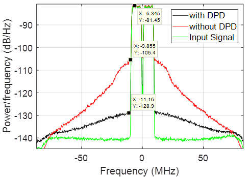
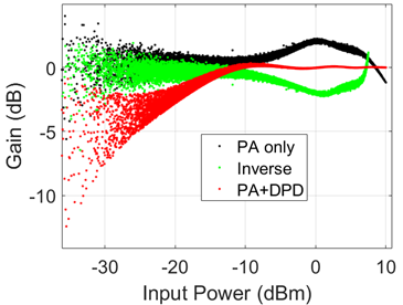
Figure 6 Shows the correction for AM/AM distortion with DPD.
The second curve relates to AM/PM distortion with DPD
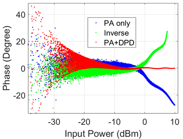
Figure 7 illustrates the Phase versus input amplitude plots with and without DPD.
The blue curve is without DPD, green curve is Inverse PA characteristic and the red curve is Phase shift with DPD+PA.
Section 5
Metrics for a DPD corrected amplifier
1. Improvement of ACPR – Adjacent Channel power ratio with the inclusion of DPD.
Improvement of the nonlinear point – the nonlinearity of the amplifier compresses the linear region of operation. The DPD provides a countermeasure and expands the linear region the outer marker is a point termed as P1dB point.
EVM – EVM is a measure of the deviation of the demodulated received symbol (I,Q) from the original transmitted data symbol (Io, Qo). The EVM magnitude is a ratio of two vector magnitude the deviation of error voltage divided by actual amplitude.
AM/AM distortion with and Without DPD
AM/PM distortion with and without DPD
Nonlinear Mean Squares error (NMSE): this is a squared difference of the PA + DPD output from the ideal output.
Loop delay accuracy and measurement: The Loop delay, time it takes to come back from PA output through ADC, DDC and back to Weight update must be known accurately for a DPD with feedback and bounded.
Xilinx Implementation of an LMS filter with 16 Taps and LMS update.
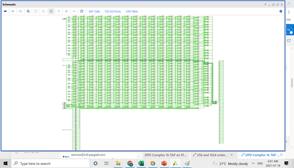
The DPD IP from SoulRA implements options of LMS, NLMS and DPD algorithms.
Section 6
DPD Interfaces
| Interface | LUT count |
| AXI-4 slave | 1670 |
| Wishbone slave | 350 |
Section 7
DPD Models Hammerstein
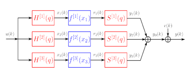
Superior accuracy for modeling an amplifier is to use a parallel Hammerstein mod
Well documented model in MATLAB for input and output data
Soul Ra will deliver a parallel Hammerstein Model in MATLAB to accurately represent the behavior of an RF Power Amp
Section 8
Support
Email: tim@soulra.net,
spondon@soulra.net